Shenzhen Chenghao TFT and Monochrome LCD Display Development and Manufacturing Processes
22 October, 2025


Search...
A sealed box is good news for dust and washdown. It is bad news for a TFT LCD module. The LEDs need power. So do the driver ICs. Neither device has a clear route to open air, and the gasket that keeps water out also keeps warm air in.
The obvious reading is the enclosure surface. Take it. Then ask what is happening inside before the heat gets there. One average case temperature can hide a hot strip along the LED edge. That strip may be aging films or adhesive while the outside of the box still feels acceptable.
Put temperature sensors where the heat is made, not only where the housing is easy to reach. The LED bar, driver package, module frame, and front glass should each have a reading. Let the unit soak at low brightness, then repeat at full. If the power supply sits close to the module, include it.
A supplier’s thermal pad drawing is a starting point. It is not proof that the pad will work in your assembly. Measure the gap after the brackets are tightened. Check whether paint, anodizing, a label, or a rubber foot sits between the module and the metal surface. Paint can look like metal and behave like insulation.
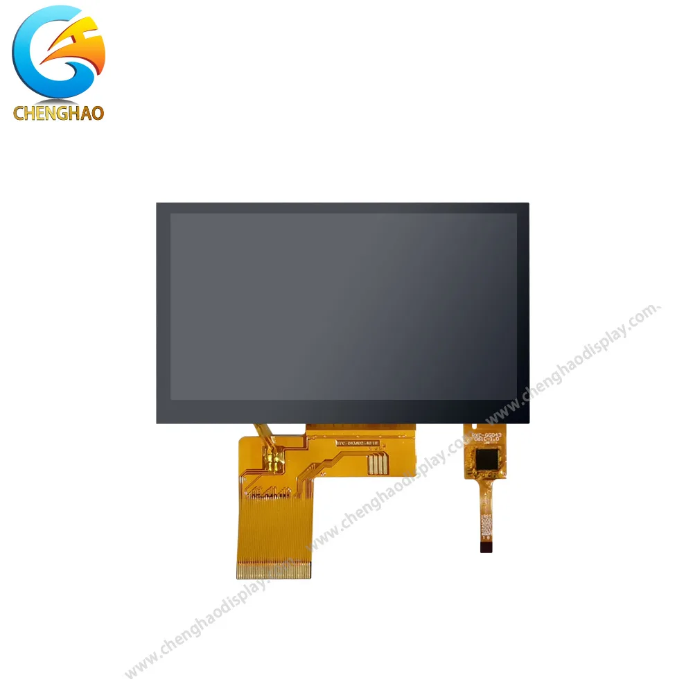
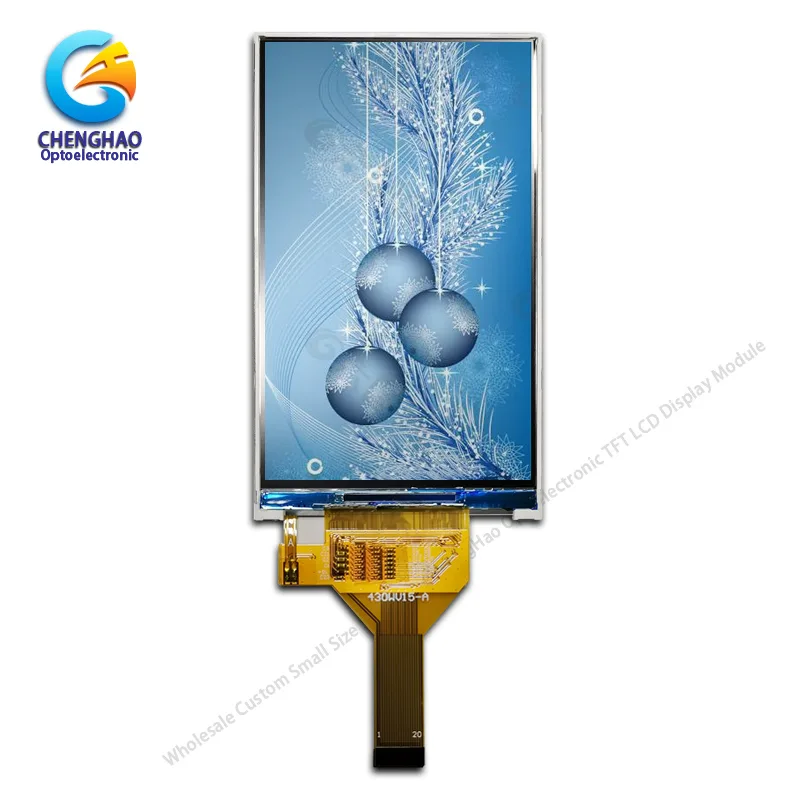
Front view of the display screen
|
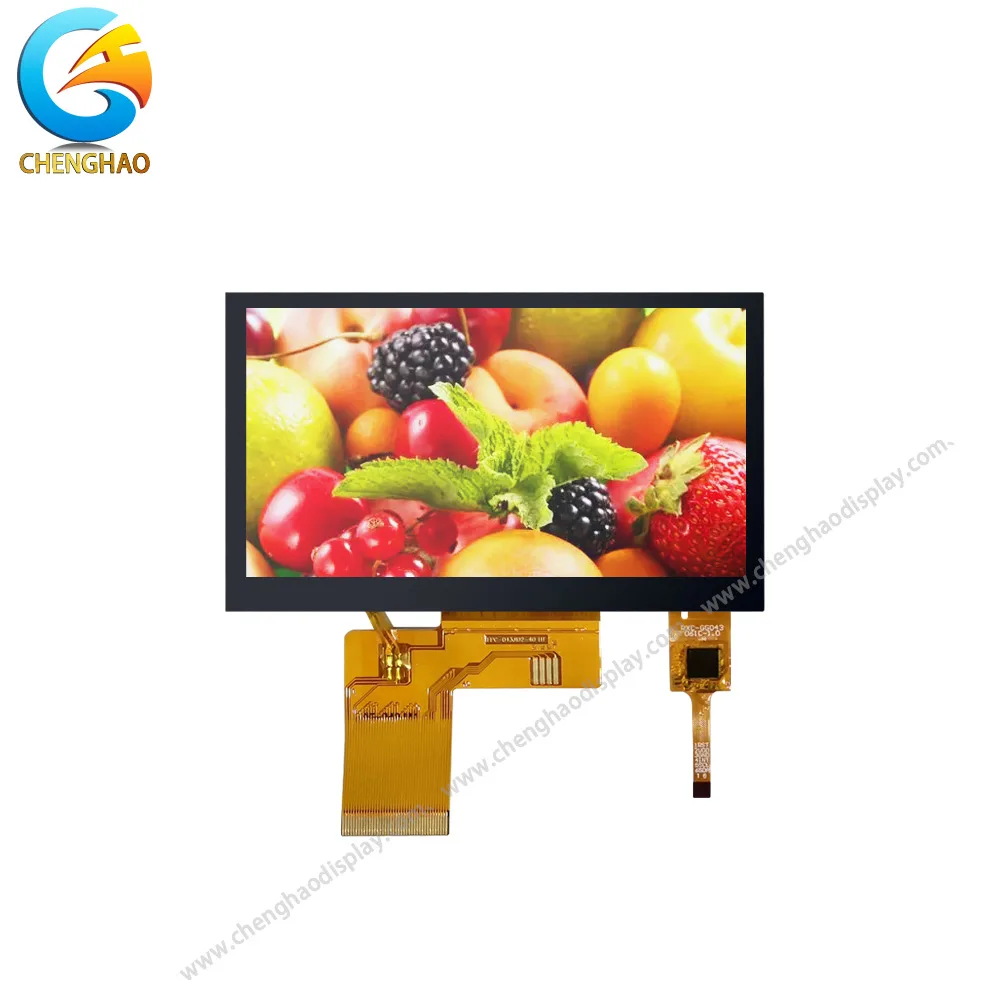
Powered-on view of the display screen
|
| CH430WV11A-CTB – 4.3 inch – TFT LCD | |
The LED edge often needs more attention than the panel center. Heat is packed into a narrow strip, so a small contact area can become a bottleneck. A metal carrier can spread that load if it connects to the enclosure. A floating plate only gives heat another place to wait.
Driver ICs create a second problem. Thermal vias and copper planes are useful when the board has a real path into a grounded bracket or chassis. They do little when the board sits on plastic standoffs with an air gap underneath. Trace the path with the same care you would give a signal return.
A thermal interface material fills microscopic gaps, but it is not a magic patch. Too little leaves an air layer. Too much can interfere with mounting pressure. Both outcomes appear when a pad is chosen without checking compression at the actual bracket load.
What happens to the LCD cell when the bracket is tightened? Force should pass through the frame or a dedicated boss, not the active area. Glass can crack or show mura under a load that looked acceptable on a drawing.
Glass is not a heat sink just because it is hard and flat. Its thermal conductivity is low, and a sharp front-to-back gradient may add optical distortion. The enclosure wall is often a better final destination because it has more area for spreading heat.
Look for a continuous metal path. Check every joint for a gap. Confirm that the pad covers the hot zone and avoids sharp edges. A powder-coated cover, thick gasket, or plastic mounting foot can break the route you thought you had.
Open-bench testing is fine for comparing early samples. It cannot show how the finished product behaves. Cable bundles change airflow. Internal supplies add heat. Foam may cover an exposed surface.
Operate the complete enclosure at the highest expected ambient temperature and the most demanding brightness, interface activity, and duty cycle. Log the trend over several hours. Does the LED edge keep rising after the outer wall stabilizes? Does the driver settle, or is it still climbing? A stable enclosure reading can conceal an unstable module.
After shutdown, let the unit cool and inspect it. Look for color shift, pressure marks, condensation, or a connector that took unexpected force. During teardown, check whether the pad stayed in place. It is easy to approve a thermal design from a drawing and find later that the pad slipped during assembly.
The measured margin should decide the next change: lower brightness, driver derating, a different bracket, or a wider conduction path. A fan is rarely the simple answer in a sealed unit. Chenghao can review the module stack, backlight, housing interface, and operating profile together. Contact us with your enclosure conditions and space limits to discuss a custom TFT LCD module.
Q1: How should we choose a thermal pad for a sealed TFT LCD enclosure?
Measure the real gap after the bracket is tightened, then confirm that the pad can fill it under the available compression. Test the completed enclosure at full brightness and the highest expected ambient temperature before approving the material.
Q2: Which areas of the module should be measured first?
Start with the LED edge and the driver package, then compare those readings with the frame, front glass, and enclosure wall. A map made at low and full brightness will show where heat is generated and where the path is interrupted.
Q3: Can Chenghao support a customized thermal and mechanical interface?
Chenghao can review the module stack, backlight, housing interface, and operating profile as part of a custom display module project. Our ISO 9001 and ISO 14001 managed production process also supports consistent quality and environmental control.