Procese de dezvoltare și fabricație a afișajelor TFT și LCD monocrome Shenzhen Chenghao
22 octombrie, 2025


Căutare...

Engleză
Engleză
A character OLED can pass every check on a workbench and still look wrong once it is fitted to a machine. The reason is rarely the panel itself. In a lab, the module usually sits at a stable temperature with a short cable and a quiet supply. The finished control cabinet offers none of those conveniences.
Begin with a direct measurement: what voltage actually reaches the display connector? A regulated rail at the circuit-board input is not evidence of anything. Connectors, cable length and the return path can all change the voltage the module sees. Measure at the connector while the display goes from a few characters to a nearly full screen, and watch two things — the depth of the dip, and how long the rail takes to recover.
Caracter Module OLED are self-emissive, though each pixel still requires controlled drive. The internal driver depends on a usable supply range, and it follows an initialization sequence defined by the module supplier. Those two details are part of the circuit design, not paperwork to file away after the module has been selected.
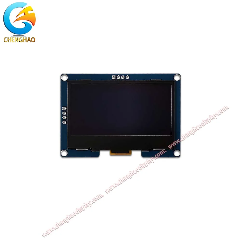
Vedere frontală a ecranului de afișare
|
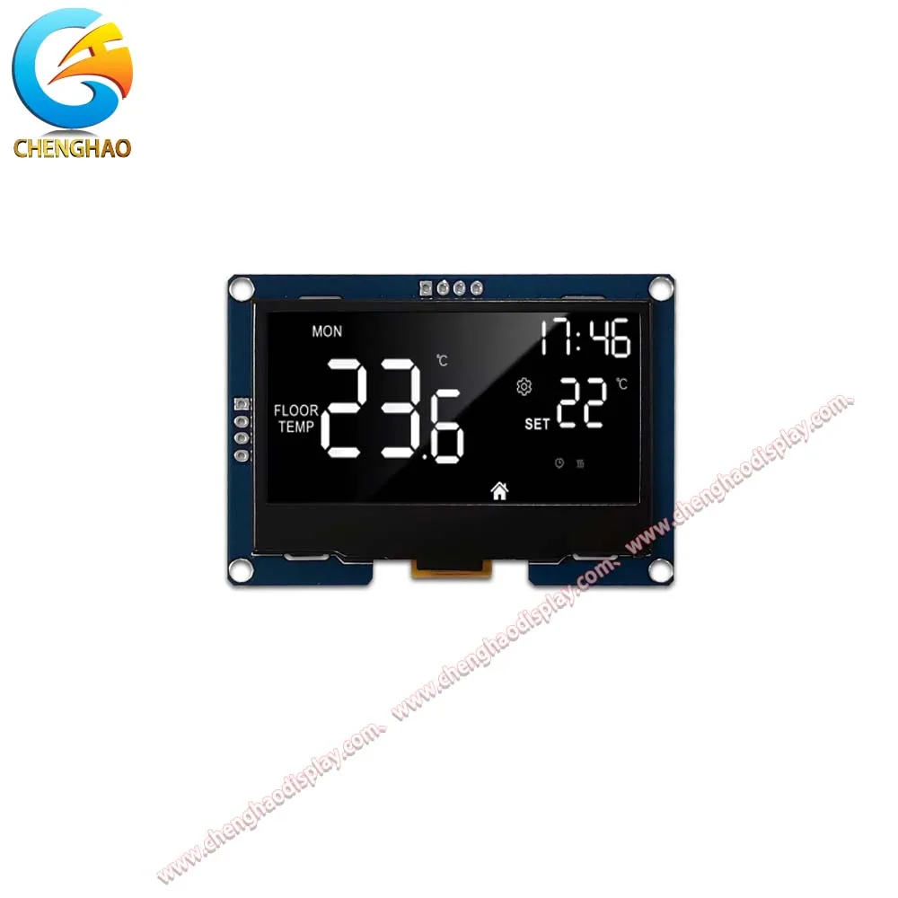
Vizualizare ecran pornit
|
| CH240L004A-PW – 2.4 inch – OLED | |
Problems often appear when a bias design is copied from one model to another without checking the driver arrangement. Two modules may look identical from the front and behave quite differently at startup — and the catalogue numbers make that concrete. The 2.42-inch 128×64 modules in this range both run from 3.3 V, yet the I2C version (CH240L002A-PW) draws up to 30.5 mA at a 105 Hz frame rate, while the SPI version (CH240L003A-PW) draws up to 35 mA at 100 Hz. Same footprint, same duty setting of 1/64, different current and different timing. A supply rail sized for one is not automatically sized for the other.
Before committing the bias circuit, get three answers from the supplier in writing:
Then test the awkward cases. Does the image flash when power is applied? Do characters remain visible after the logic rail drops? A fault here is usually timing rather than image quality. Three things make power-up and power-down more predictable:
The contrast command is easy to treat as a software preference. In reality, the visible result combines emission response, scan waveform, supply voltage and ambient temperature. A value selected in a comfortable office may be too bright inside a closed cabinet and too weak during a cold-start procedure.
Vedere frontală a ecranului de afișare
|
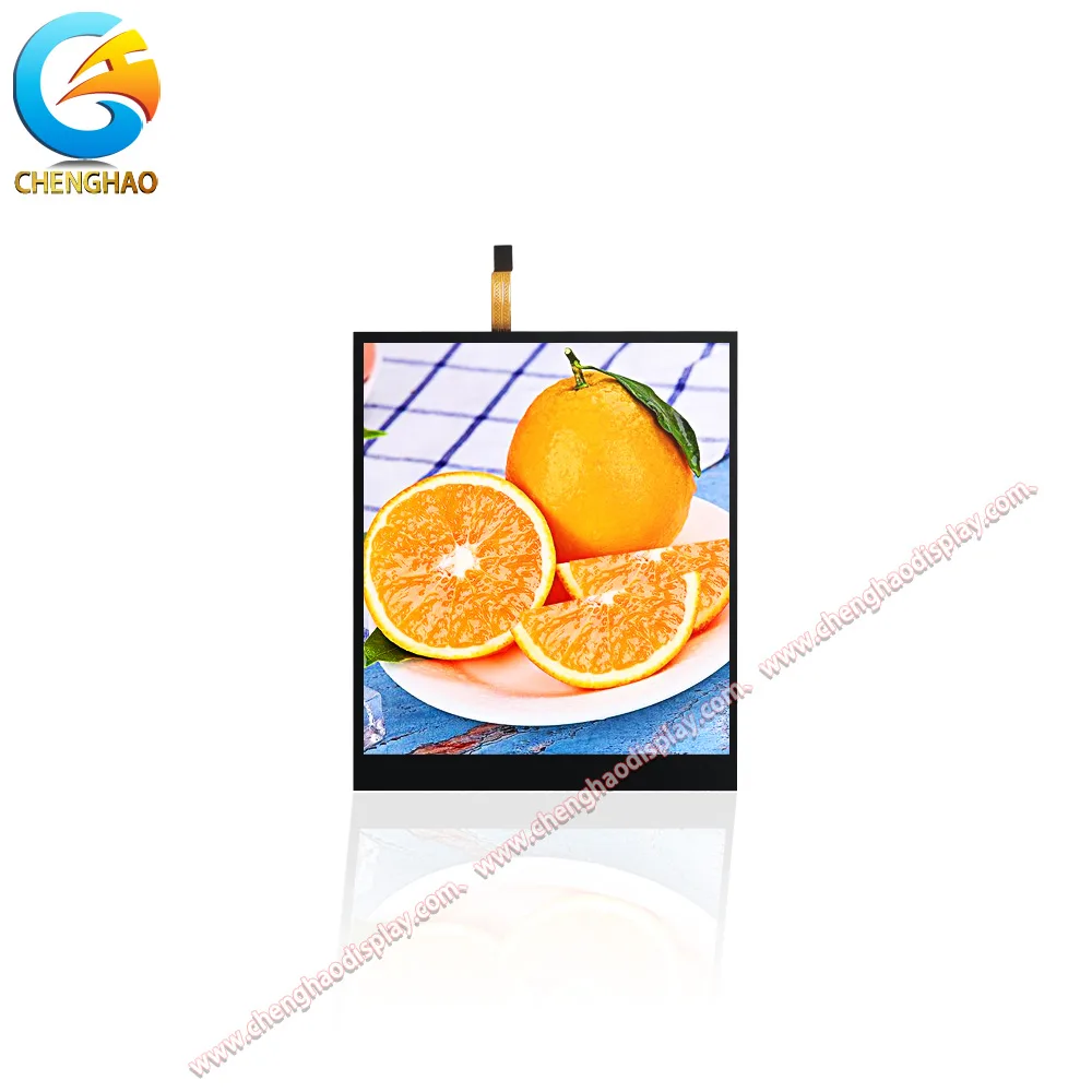
Vizualizare ecran pornit
|
| CH400OL02A-CT – 4.0 inci – OLED | |
Run the calibration with the firmware routine that will actually ship, not a bench utility:
A single golden value hides normal variation, and it sends service teams toward the wrong board when a unit looks different but is behaving normally. The storage range matters here too: the 2.42-inch modules in this catalogue are rated −40 °C to +70 °C operating with −40 °C to +85 °C storage, so a cold-start sequence can begin from a condition well outside the operating window.
Pay attention to pattern changes as well. A screen alternating between sparse text and dense rows draws different current. If a capacitor near the connector is doing all the work, voltage movement shows up as faint bars or uneven brightness rather than as a clean image. The supply and return path need margin for that changing load, not just for the average.
The production harness belongs in the electrical review, not only in the mechanical one:
A clean test fixture can conceal a connection problem that the customer will find later. At the software level, protect contrast and initialization values from accidental change, record how they are restored, and validate each approved module variant. Industrial panels often stay in service long enough for replacement parts and board revisions to enter the supply chain, and clear settings are what make those changes survivable.
Chenghao Optoelectronic supports character OLED and custom display module projects from selection through SMT assembly and module testing, with ISO 9001 and ISO 14001 quality systems. Bring the supply plan, harness drawing, enclosure conditions, and contrast target to the review. Contact us to choose a character OLED module that can support the full control-panel design.
Q1: How can engineers investigate low contrast in a character OLED module?
First measure the supply voltage at the display connector under several character patterns, watching both the depth of the dip and the recovery time. Then compare the bias timing, initialization sequence and contrast setting with the module documentation and the final product configuration.
Q2: Why does character OLED contrast differ between units or temperatures?
The visible result depends on emission response, scan waveform, supply voltage and ambient conditions. Establish an accepted contrast range across the operating temperature and across production samples, rather than relying on one fixed setting.
Q3: Why do characters stay visible after the logic rail drops?
Because the rails are not falling in a defined order. Without a planned discharge path and an enable signal that gates the driver, residual charge can keep the panel emitting after the host has shut down. Correcting the power-down sequence usually resolves it; it is a timing issue, not an image-quality issue.
Q4: What should be reviewed for a customized character OLED module?
Share the supply architecture, enclosure temperature, viewing requirements, harness details, contrast target and expected production volume. A joint review can align the display choice, drive circuit, initialization routine and quality controls before tooling is committed.