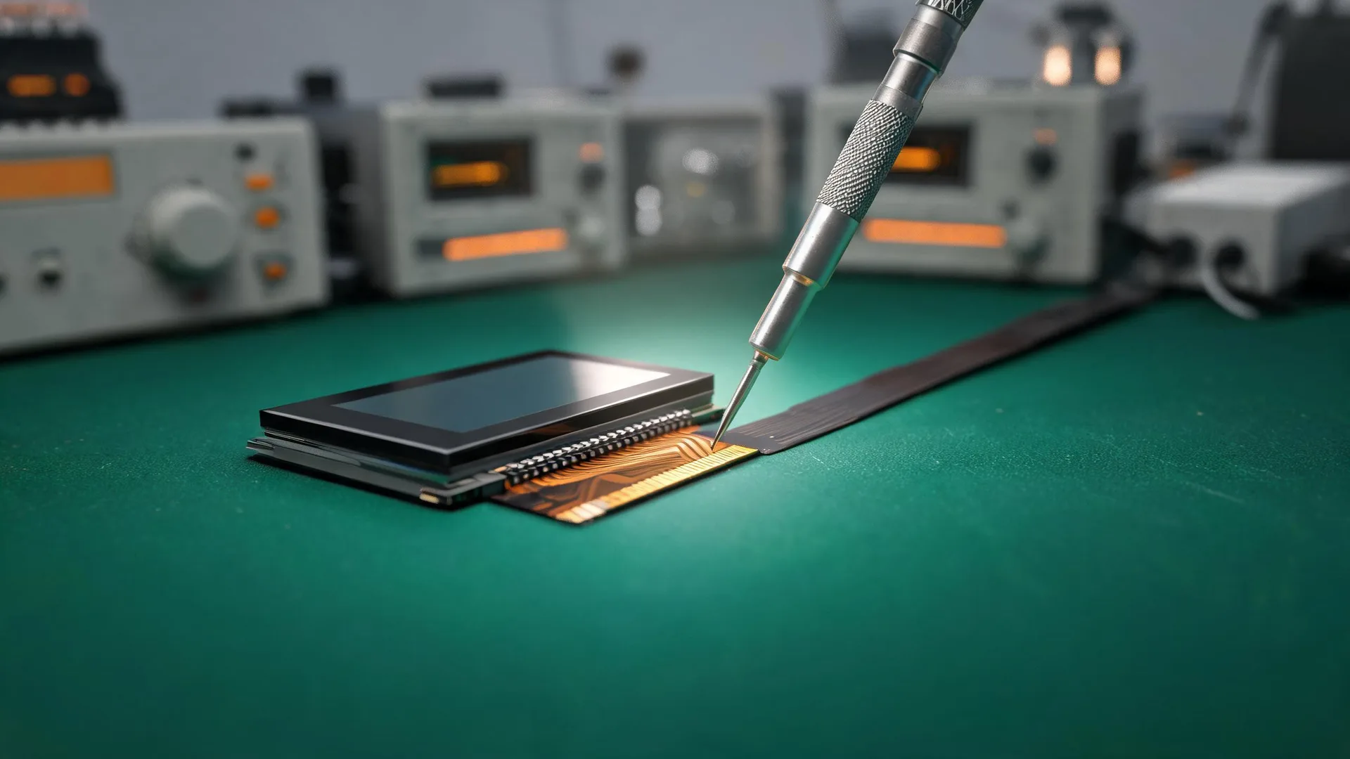
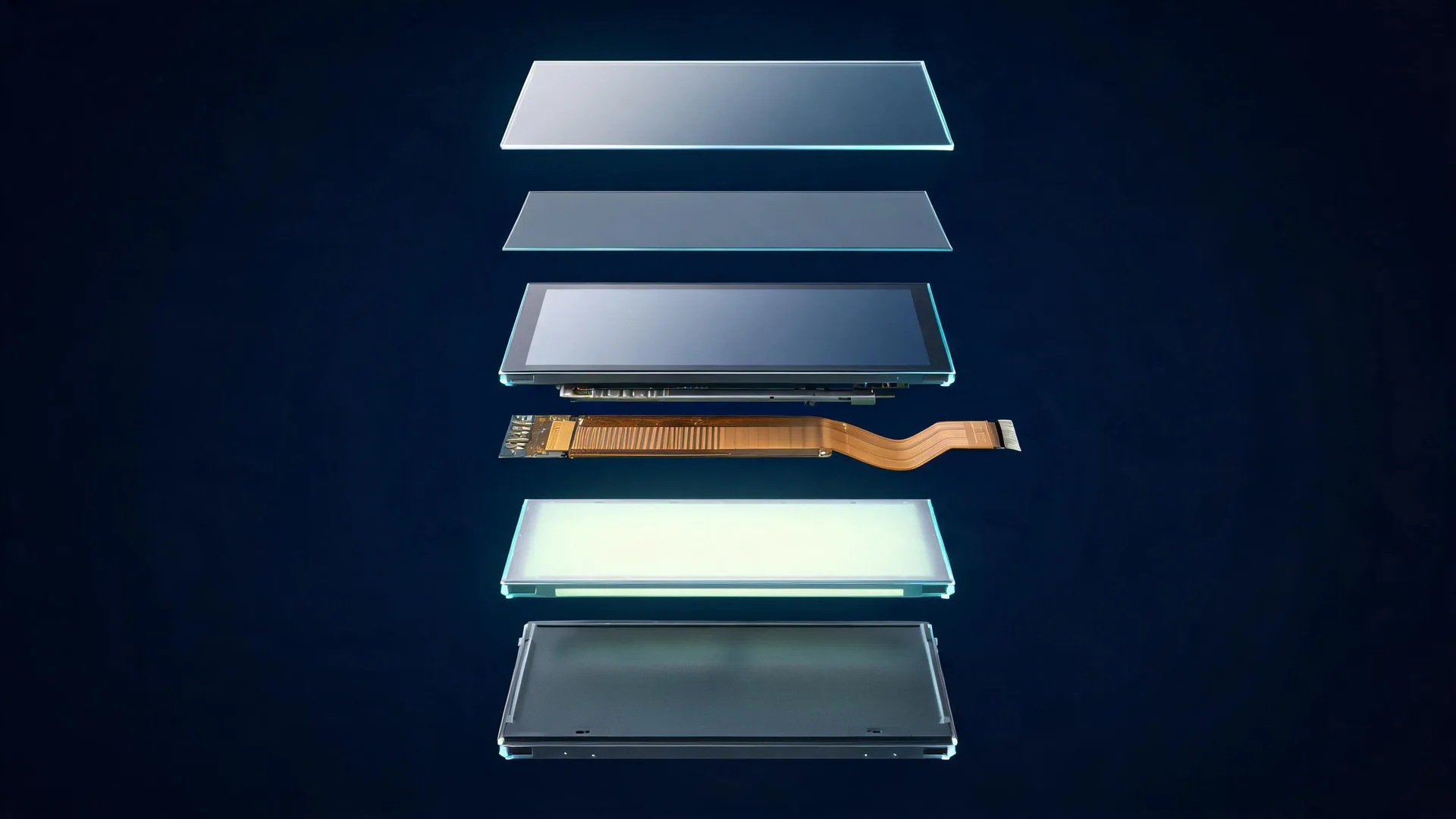
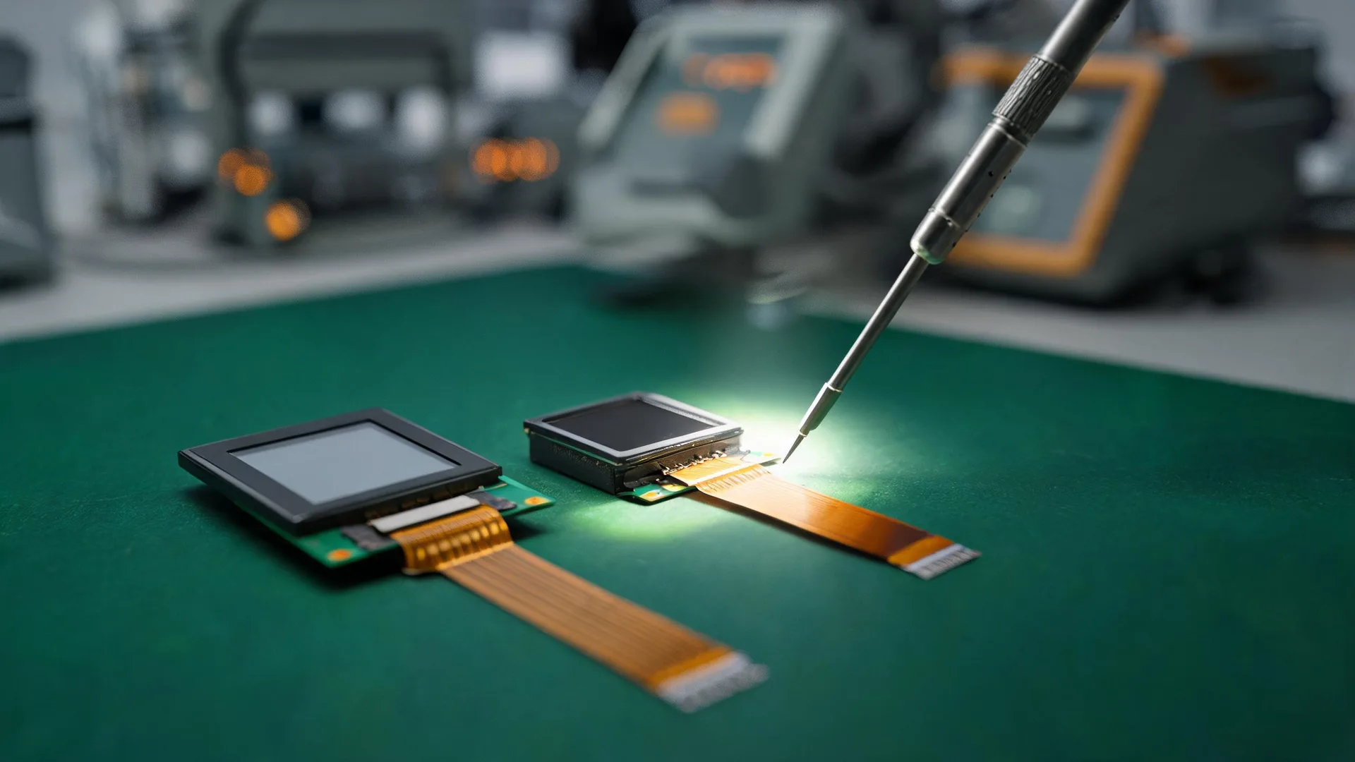
Shenzhen Chenghao TFT og monokrome LCD-skærmudviklings- og fremstillingsprocesser
22 oktober, 2025
What happens when an embedded instrument leaves the same warning icon glowing for an entire shift? The answer can expose a problem that a startup check never sees. One corner may look slightly warmer than another. A thin delimiter may fade against the background. None of the readings are wrong, yet the operator hesitates. That is why OLED module luminance uniformity has to be judged on the installed, running product.
Engineers often start with a full white image. It is a sensible baseline, and it can reveal a dead region or an obvious dark band. It does not tell you how the screen behaves after hours of mixed content. Nor does it show whether a bright alarm icon will remain visually separate from a low-output status bar.

Forfra af skærmen
|

Tændt visning af skærmen
|
| CH091L002A – 0.9 tommer – OLED | |
Picture an instrument left on a monitoring page. The upper half holds a live chart. A small value updates in the corner. The rest of the screen stays dark. After enough time, those regions have different operating histories. Organic emitters can change with use, and individual pixels do not necessarily respond in the same way. A controller sending one drive value everywhere has no way to account for that spread.
The viewing condition matters too. A control room, a covered service panel, and a window-side station put different demands on contrast. Before selecting a module, write down the normal page, the least readable warning state, and the ambient conditions the operator actually faces.
Measured compensation is one useful tool. A controller can apply correction data to pixel groups when its memory and processing budget allow it. The catch is traceability. A correction map belongs to a particular panel family, driver setup, and firmware release. Moving that file into an unverified build may create a new pattern instead of fixing the old one.
Supply routing can produce a pattern of its own. Pixels far from the connector may see a different voltage than pixels close to it when several bright elements switch on together. Low-content screens may hide the effect. If a prototype looks fine in a menu but uneven on a dense graph, compare the return paths before blaming the panel.

Forfra af skærmen
|

Tændt visning af skærmen
|
| CH049L001A-PW – 0.5 tommer – OLED | |
Heat takes longer to reveal. Nearby power components can warm one side of the housing while the front cover cools at a different rate. When brightness drift follows a hot area, measure the installed module. A bare-panel test on an open bench can miss what the enclosure is doing.
Content can reduce the risk without changing hardware. Use shape or color alongside luminance for critical states. Avoid making every page produce maximum output when a lower default level is enough. Thin borders deserve attention because slight variation is easy to see against a dark field.
Keep the test states repeatable and note the conditions. Start with one uniform field, then move to patterns and the actual instrument interface. The important comparison is across time and temperature, not just across one image.
During incoming inspection, a short sequence can catch an obvious mismatch between the panel and its configuration. A longer qualification run can look for local load effects and temperature drift. Neither test needs invented performance figures. The useful output is a clear record of what changed, under which conditions, and with which build.
Chenghao Optoelectronic supports custom OLED and TFT LCD module integration from 0.91 inch for embedded instruments. Our team can review interface, driver, and mechanical requirements against the enclosure and operating cycle. Send the display size, normal screens, and expected runtime to plan the next uniformity check. Contact us to discuss your module configuration.
Q1: How should we define OLED luminance uniformity for a custom instrument?
Start with the normal screen, each critical warning state, the expected ambient conditions, and the enclosure’s operating temperature. Share those requirements so the panel, driver, and interface can be reviewed together.
Q2: Can a custom OLED module include compensation and a different interface?
Yes, when the selected controller and memory budget support the correction method. The compensation map should be created and verified for the exact panel family, driver configuration, and firmware release.
Q3: How can buyers keep sample and production performance consistent?
Tie every unit to a shared panel, driver, firmware, and calibration record, then repeat the same reference image set at incoming inspection. Chenghao Optoelectronic’s ISO9001 and ISO14001 systems support controlled module integration and change review for embedded projects.