Shenzhen Chenghao TFT və Monoxrom LCD Ekran İnkişafı və İstehsal Prosesləri
22 oktyabr, 2025


Axtarış ...
Audience: Hardware engineers, system integrators, industrial HMI designers, validation and procurement teams | Published on company technical blog
Working with industrial displays day in and day out, I’ve noticed how often people mix up burn-in and image sticking. It’s a really common confusion out in the field. OLED and old CRT units can develop true permanent burn, but LCD panels don’t behave that way. That said, leave a static graphic running nonstop for days, and faint ghost impressions will very likely show up on the screen.
This difference isn’t just some picky wording thing we put on datasheets for formality. It actually guides the whole qualification workflow we build. We set acceptance limits and add protective features specifically for gear that runs around the clock: HMIs on the factory floor, continuous dashboards, static signage and embedded hardware stuck showing the same UI for weeks on end.
If you look through support tickets, you’ll see technicians often label temporary sticking as burn-in. That casual label creates confusion. QA, production teams and end users all end up with different expectations about what is normal and what counts as a failure. This write-up covers the physical reasons this effect happens, practical test methods we use in our lab, how to recover affected panels, and the design compromises you’ll need to weigh for your next display project.
When our team writes test specs, we start by locking down consistent terminology. Shared definitions cut down on endless back-and-forth whenever we review test reports and component specifications.
Genuine burn-in comes from irreversible damage inside emissive pixel materials. Once that damage occurs, the mark stays there for good. Changing what’s shown on screen, power cycling or leaving the unit powered off for long stretches won’t make it disappear. You see this failure mode on self-emitting technologies: OLED, AMOLED, QD-OLED, older plasma displays and classic CRT screens.
Image retention, or sticking / ghosting as many of us call it, is a reversible visual quirk for LCDs. It develops when liquid crystal cells hold residual bias effects after a static voltage has been applied for a long time. As long as you stay within the operating range the panel supplier defines, these faint marks fade naturally over time. Playing moving content or fully powering the display down for a while usually clears the ghosting completely.
I run into this naming confusion all the time when hardware returns come in. Customers and field techs almost always call this temporary sticking burn-in. Before starting formal failure analysis, the first thing I check is whether what I’m seeing is recoverable retention or permanent material damage.

Ekranın ön görünüşü
|

Ekranın işə salınmış görünüşü
|
| CH130-2864KSWLG22X VER – 1.3 düym – OLED | |
These two defects act very differently. OLED burn accumulates gradually and cannot heal at all. LCD sticking builds up under long static bias, and fades when the screen shows varied content or rests. Temperature affects both, but not in the same way. Higher operating temperatures make LCD sticking appear faster, yet they also speed up recovery. For OLED panels, heat only speeds up permanent degradation.
They also tend to pop up in different use cases. Static HMIs and fixed dashboards are the highest-risk environment for LCD sticking. Persistent overlay graphics, like status bars and game UI overlays, are well-known triggers for OLED burn. Our fixes for each are separate. On LCD projects, we focus heavily on Vcom tuning and polarity balance control. OLED systems rely on pixel shifting, brightness caps and runtime throttling to slow wear.
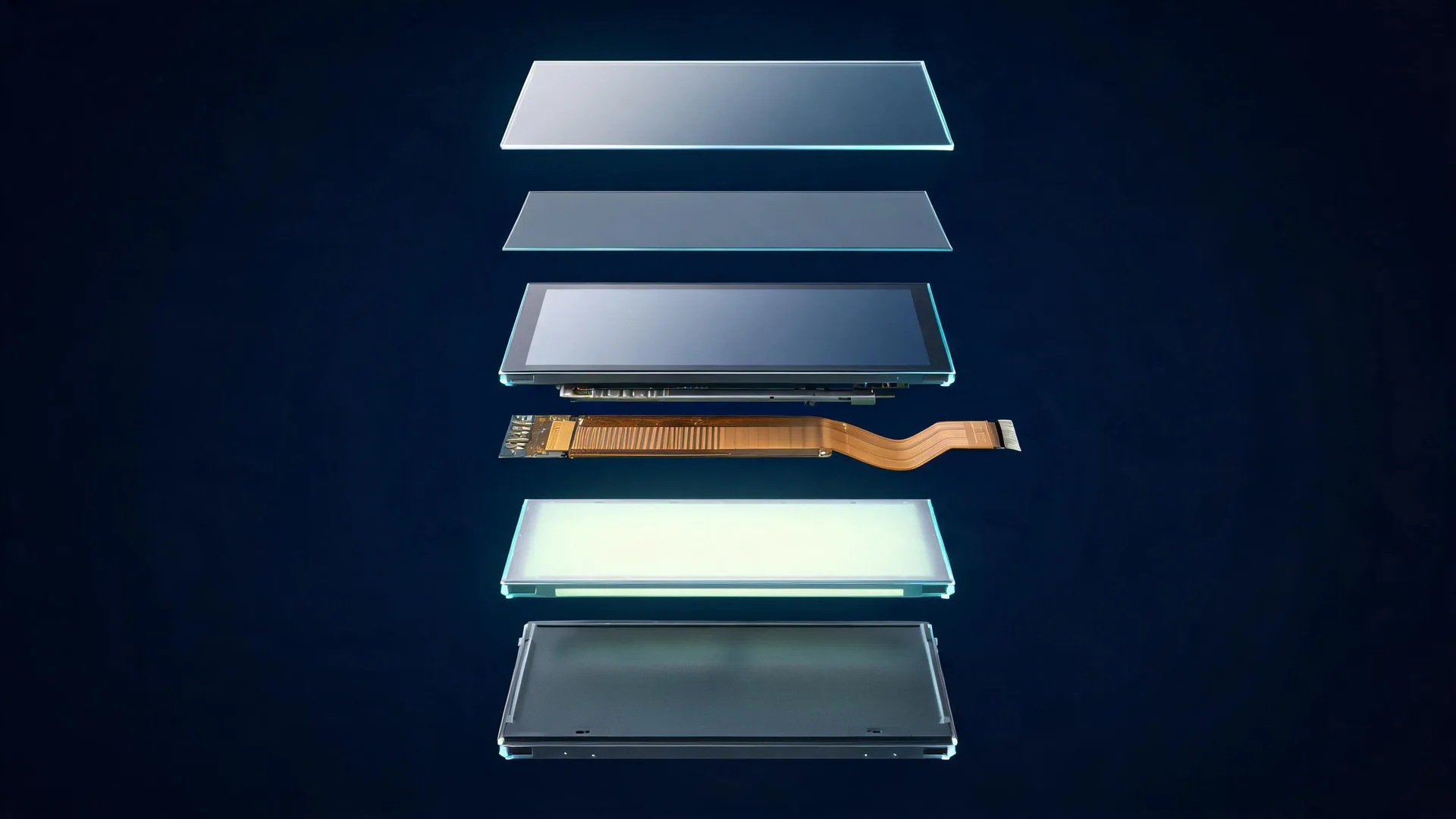
LCDs don’t create light themselves; they modulate light from a backlight. Light passes through polarizer films, color filters and the liquid crystal layer. Each pixel controls light transmission by twisting liquid crystal molecules, following the drive voltage sent to it.
When a region of the screen holds the same voltage level for dozens, even hundreds of hours, a few physical effects stack up.
First, tiny ion contaminants inside the liquid crystal drift slowly toward ITO electrodes and the polyimide alignment layer. This drift creates a leftover static electric field even after the driving signal changes. Liquid crystal molecules can’t snap back fully to their relaxed orientation, leaving a faint copy of the old static pattern.
Second, the alignment film builds weak polarization memory. This polyimide coating sets the default resting angle for liquid crystal molecules. Holding a steady electric bias long enough slows how quickly those molecules relax.
Panel architecture changes susceptibility too. IPS and FFS panels are popular for wide viewing angles, but they pick up visible sticking much easier than older TN designs. Their in-plane electrode layout creates uneven local electrical fields, which build unwanted DC offset quickly. VA panels sit somewhere in the middle in terms of risk.
One myth I regularly correct: fast response time does not stop sticking. Response time describes how quickly pixels switch state on each refresh. Retention builds slowly, over hours of steady static voltage load. I’ve tested industrial panels rated for 1ms switching that developed clear ghosting after three straight days showing the same HMI screen.
There’s one lookalike issue you need to watch for. After years running at high brightness, individual LEDs inside the backlight degrade unevenly. The resulting brightness pattern looks almost identical to retention, but it comes from LED aging, not the liquid crystal layer. This backlight wear won’t recover with rest time.
A really common mistake during qualification: teams run a quick checkerboard test and sign the panel off. That approach fails to replicate real-world risk. Your acceptance criteria need to match your actual product environment: operating temperature, target brightness, the real UI your device runs, and how long static elements stay active once deployed.

Ekranın ön görünüşü
|

Ekranın işə salınmış görünüşü
|
| CH154OL002W-PA – 1.5 düym – OLED | |
This is the test flow our team uses for industrial display qualification, aligned with standard SID guidance.
Let the panel reach full thermal stability at its maximum rated operating temperature and target brightness.
Load your production UI or high-contrast stress pattern and run continuously for your agreed soak period. 12, 24 and 48-hour soak times are common, picked based on how the end device will be used.
Immediately switch the panel to a uniform 128-level grey field (50% grey). A flat grey background makes faint ghost artifacts much easier to spot visually.
Carry out visual checks from a fixed distance, under consistent ambient lighting. Log results at set checkpoints: right after the stress run ends, plus 5 minutes, 30 minutes, 2 hours and 24 hours later.
Record ghost visibility, contrast strength, full recovery time, panel temperature, Vcom setting and inversion scheme.
Run a control test with constantly moving content, to rule out human visual afterimages. This optical aftereffect fades within seconds and is not a defect of the panel itself.
You can adapt this requirement for your SOW: After a 24-hour static high-contrast stress run at rated brightness and maximum operating temperature, any visible residual image must become undetectable within 60 minutes on a uniform 128-grey screen.
If retention shows up during lab testing or on returned hardware, work through these checks before marking the panel defective.
Play moving video or randomized dynamic patterns at normal brightness, for one to four hours.
If the ghost remains, cut full mains power to the display — standby power is not sufficient — for 4–12 hours. This gives trapped ions time to redistribute naturally.
Cycle the panel showing a flat grey screen. Many industrial controller ICs include this refresh function built for exactly this scenario.
Double-check Vcom voltage and frame inversion balance. Poorly tuned Vcom offset is one of the top causes of excessive sticking, even on otherwise reliable panels.
If the mark stays visible after multiple recovery cycles, you are no longer dealing with standard temporary retention. Check for uneven backlight LED wear, polarizer thermal damage, or rare permanent degradation of the alignment layer. This scenario is uncommon for properly qualified industrial LCDs operated within datasheet limits.
These practical steps reduce sticking risk for equipment that runs static interfaces 24/7.
Tune Vcom carefully and confirm balanced frame or column inversion. Unbalanced inversion builds up net DC bias over time, and it’s high on our root cause checklist for bad retention performance. Verify your TCON chip holds stable polarity balance over long runtimes.
Use pixel shift, also known as pixel orbiting. Shift static logos, status bars and fixed text areas one or two pixels on a timer. This spreads electrical load across neighboring subpixels without users noticing any visual change.
Add an idle screensaver that switches to a flat grey field after a custom timeout, built for always-on HMI systems.
Lower brightness on UI zones that stay static. Retention risk climbs together with brightness and contrast difference.
If functional requirements allow it, avoid sharp high-contrast borders and pure white graphics on fully black backgrounds.

Ekranın ön görünüşü
|

Ekranın işə salınmış görünüşü
|
| CH400OL001A – 4.0 düym – OLED | |
Animate non-critical static elements slowly when possible. Soft fades or slowly incrementing counters break up continuous fixed bias.
Cycle different screen layouts automatically if your workflow allows it, so no single graphic stays locked forever.
For hardware running static screens nonstop, choose industrial-grade panels made with low-retention liquid crystal blends and specialized alignment films.
Trade viewing angle performance against retention risk during design reviews. IPS panels deliver great viewing performance, but they have higher sticking risk for static UI work compared to TN panels. VA panels fall between them.
For signage and dashboards where even faint ghosting is unacceptable, run retention stress tests on your exact production panel batch before mass release.
Can LCD panels ever develop permanent marks? It can happen under extreme conditions, but it is not the same burn-in you see on OLED. Permanent defects usually come from years of continuous high-brightness operation, thermal overload, or uneven backlight aging. Quality industrial LCDs used within datasheet limits almost never develop permanent liquid-crystal ghosting.
Does a Mini-LED backlight make LCD immune? No. Mini-LED is still an LCD architecture. The liquid crystal stack can still develop image retention. Local dimming zones carry their own risk; holding one zone at peak brightness for years leads to uneven LED degradation.
Is temporary image retention covered under warranty? Most component suppliers consider fully recoverable retention, seen within datasheet operating limits, a normal electro-optical characteristic of liquid crystal technology, not a hardware fault. Make sure this point is clear early in your quality agreement and SOW.
Does the standard checkerboard test match real customer risk? Checkerboard patterns work well to rank different panel samples side by side. The most meaningful qualification always uses your actual production UI. Retention risk depends heavily on contrast, color, brightness, plus the shape and layout of static elements in your interface.
LCD is generally safer than OLED for devices that run fixed UI screens continuously, because its ghosting can recover. Even so, “safer” does not mean zero risk.
If your product uses high-contrast static UI elements that stay active all the time, include retention testing in your DV and PV plans. Validate Vcom and inversion tuning, and add safeguards like pixel shift or idle grey screens.
When a field report mentions burn-in, don’t immediately swap parts. Run the recovery procedure first. In most cases, what you see is predictable, testable, and preventable with thoughtful system design. Image retention is an engineering constraint, not a fatal flaw for LCD technology.
If you are building an HMI, dashboard or signage product and need engineering support, our display team can create custom retention test specs, adjust Vcom and inversion parameters, or help you pick panels that fit your operating requirements. Reach out via our contact page, and we can talk through your display needs.
Q1: What is the difference between LCD image retention and burn-in?
LCD image retention is usually reversible ghosting caused by residual charge and slow relaxation in the liquid crystal stack. True burn-in is permanent damage to emissive pixel materials and is associated with OLED, plasma, and older CRT technologies. A faint LCD mark that fades after dynamic content or a full power-down is retention rather than permanent burn-in.
Q2: How should a production display be tested for image retention?
Test the actual product UI at rated brightness and maximum operating temperature until the panel is thermally stable. After the agreed stress period, show a uniform 128-level grey field and record the mark at fixed checkpoints until it clears. Compare the result with an acceptance limit agreed in the project specification rather than relying on a generic checkerboard result.
Q3: Which engineering controls reduce LCD image retention risk?
Balance Vcom and frame inversion, shift static interface elements by one or two pixels, add an idle grey screen, and reduce brightness in persistent UI zones. Panel selection also matters because IPS and FFS configurations can be more susceptible than TN under long static bias. Validate the selected production build with a realistic retention test.