Shenzhen Chenghao TFT and Monochrome LCD Display Development and Manufacturing Processes
22 October, 2025


Search...
Anyone who has spent time building embedded HMI hardware knows one particular scenario very well.
You lock in your MCU, finish the mechanical housing, route your PCB, and pick a capacitive touch panel that looks decent from a vendor. On the bench, everything works great. Taps, swipes, all responsive.
Then you drop the assembly into its real operating environment. Motor noise from nearby factory equipment. Temperature swings. Random splashes of water. Operators wearing thick work gloves. Or that longer FPC you had to add just to fit the mechanical stack. That is when the problems kick in: ghost touches, dead spots, jitter, touch cutting out for no obvious reason.
Almost none of these are sensor defects. Each one changes the capacitance the controller is measuring, and the controller reacts by recalculating its baseline until a real finger press no longer stands out from the surrounding noise. The panel still meets its datasheet. The system around it does not meet the panel.
Debugging touch issues can eat weeks of a schedule. Many suppliers hand over a generic datasheet and stop there, offering no firmware guidance and no help with the integration problems that only appear inside your own enclosure. What follows is the shortlist of checks that separates a panel which demos well from one that ships in volume, covering HMIs, portable test gear, medical accessories, smart gateways, battery-powered handhelds and industrial control screens.
Lots of engineers start searching by display inch size. For PCAP touch, that approach often backfires, because the constraint that kills a project is almost never the diagonal measurement.
Before sending out RFQs, get your hard requirements sorted out:
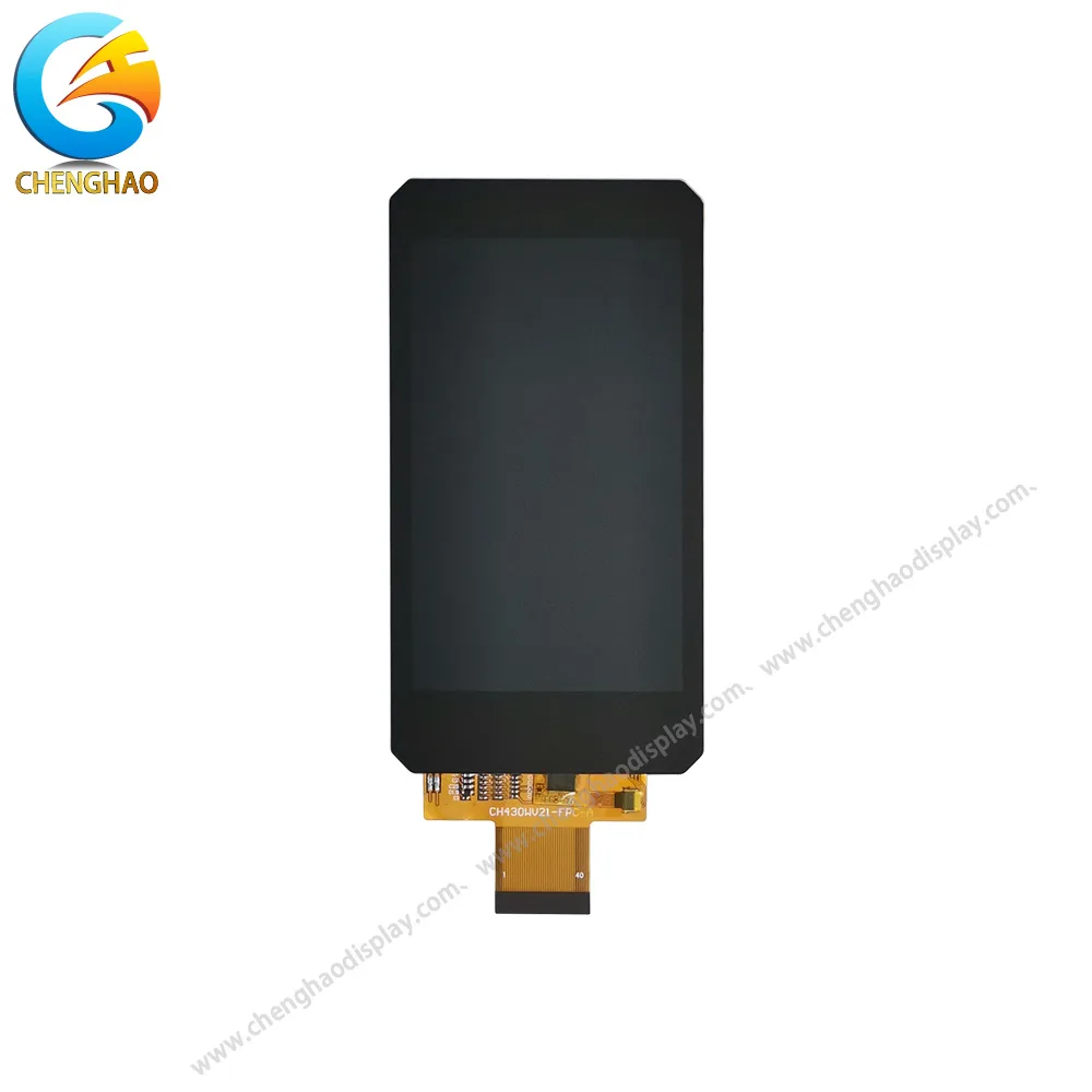
Front view of the display screen
|
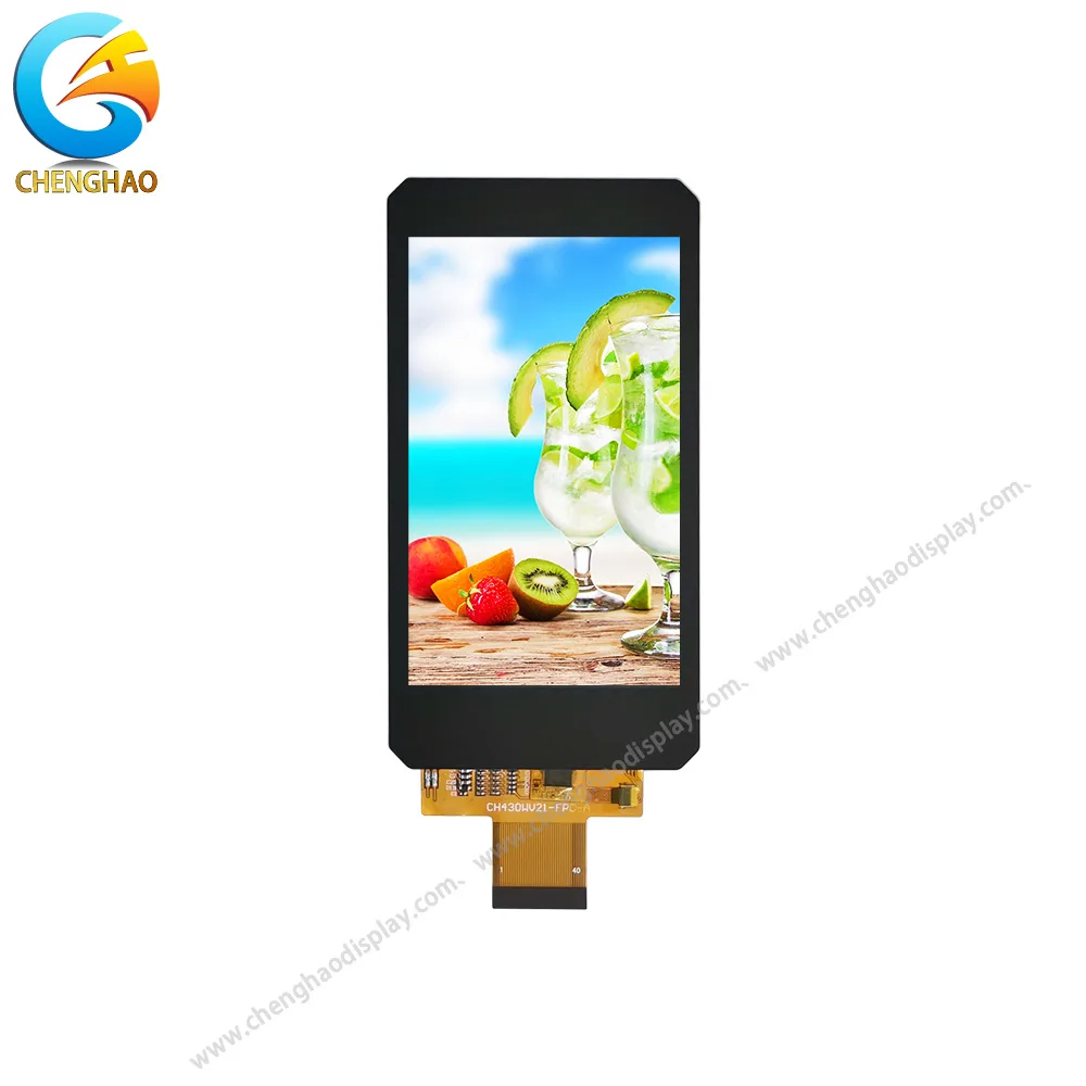
Powered-on view of the display screen
|
| CH430WV21A-CT – 4.3 inch – TFT LCD | |
At Chenghao Display, the technical team does not lead with stock panels on an inquiry. That background gets asked for first. A 4.3″ GT911 I2C touch that behaves perfectly on an indoor IoT unit can act unpredictably on industrial hardware once the controller parameters have not been tuned for electrical noise.
The touch IC sets most of your noise margin. The sensor layer matters, certainly, but filtering, auto-calibration, water rejection and glove algorithms all live inside the controller firmware.
For embedded designs, mature ICs from the Goodix GT series and FocalTech FT series cover most requirements. When vetting a supplier, these are the questions that actually separate candidates:
A supplier worth working with will discuss tuning trade-offs. Others answer “multi-touch supported” and stop there. PCAP modules are often pre-tuned around a customer’s exact stack, particularly where thicker cover glass or optical bonding is involved, which avoids the classic trap: the sensor passes on a thin demo lens and loses sensitivity the moment the production front glass goes on.
PCAP performance is really sensitive to the full optical stack. G+G glass-on-glass construction is usually the safer choice for industrial, medical or outdoor equipment: harder to scratch and more dimensionally stable over the life of the product.
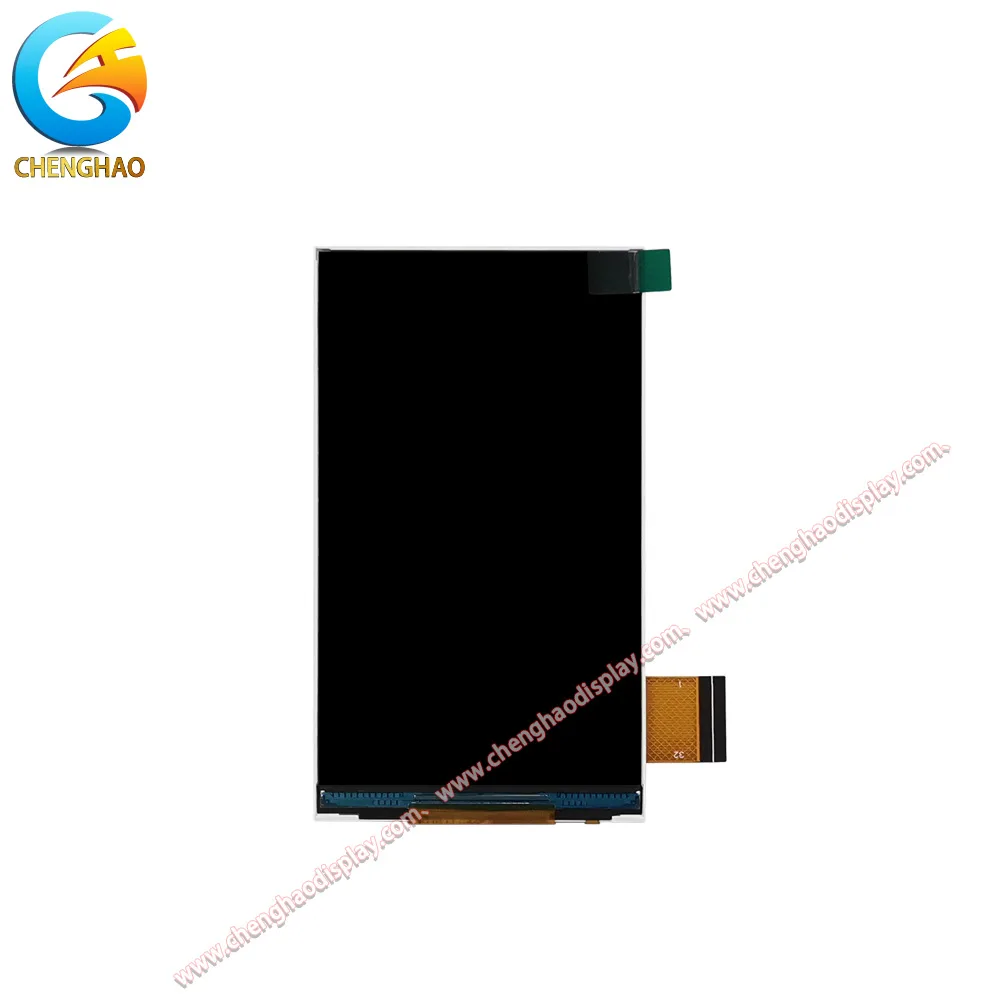
Front view of the display screen
|
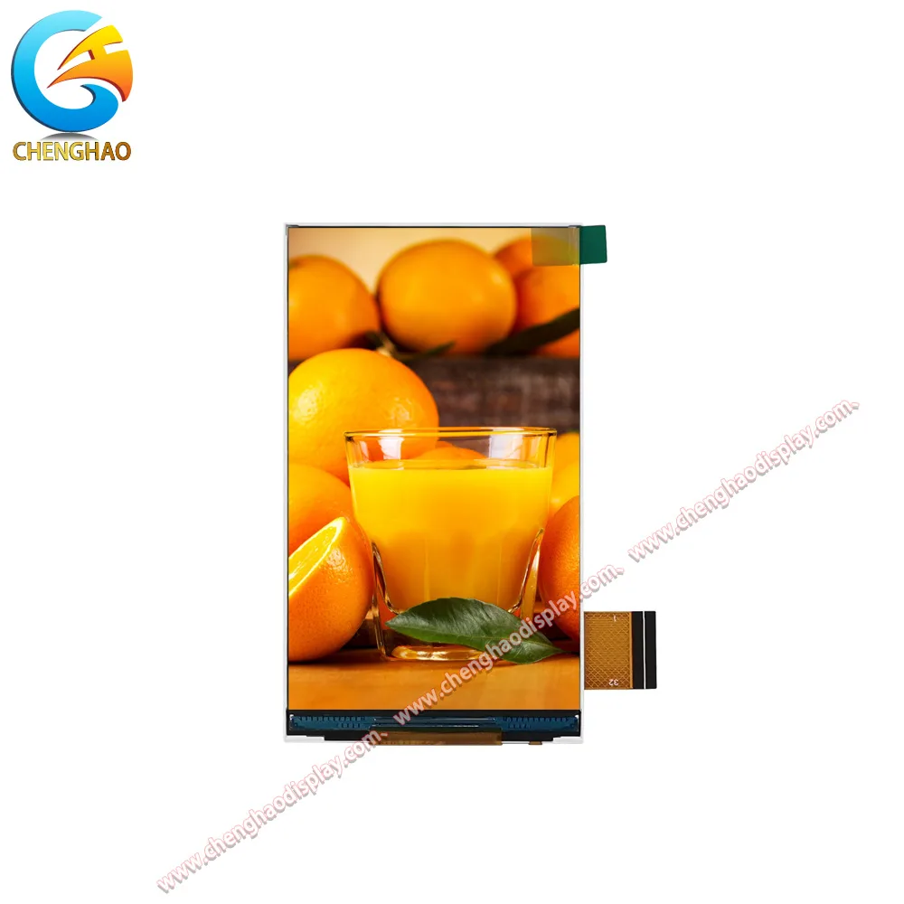
Powered-on view of the display screen
|
| CH450FW05A – 4.5 inch – TFT LCD | |
Optical bonding removes air-gap reflections, cuts fogging risk and keeps touch stable under vibration. It costs more and carries longer lead times. Air bonding is adequate for low-cost indoor products where the enclosure environment stays consistent.
Cover glass thickness is easy to overlook. Above roughly 1.5 mm, controller recalibration is almost always required. State that requirement up front, and don’t assume an off-the-shelf module will drive a custom cover plate.
On surface treatment: anti-glare helps under bright light, anti-fingerprint makes sense where operators handle the unit constantly. One detail usually left out of the brochure, AG etching attenuates the touch signal slightly, so firmware compensation is part of the design rather than an afterthought.
FPC detail deserves the same attention: total length, minimum bend radius, pin map and connector type. Long FPC runs are one of the quiet causes of EMI and touch drift. Routing, shielding and pin definitions can be matched to your PCB footprint before production, which is the difference between an adjustment and a board re-spin.
A datasheet line saying −20 °C to +70 °C operating range does not mean much on its own. Parts exist that hold electrical continuity at both limits while touch response degrades badly.
Ask to review test records covering:
One point worth stressing: these tests still have to be repeated on your full assembly. PCB, cable, enclosure and power supply all change the system behaviour, and most touch glitches originate in system noise rather than in the panel. Good suppliers share their test methods so you can replicate and debug the same conditions.
This is where many overseas teams hit a wall when buying from generic vendors. What you need, in writing rather than in conversation:
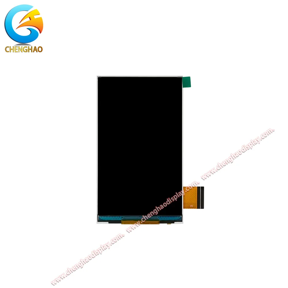
Front view of the display screen
|
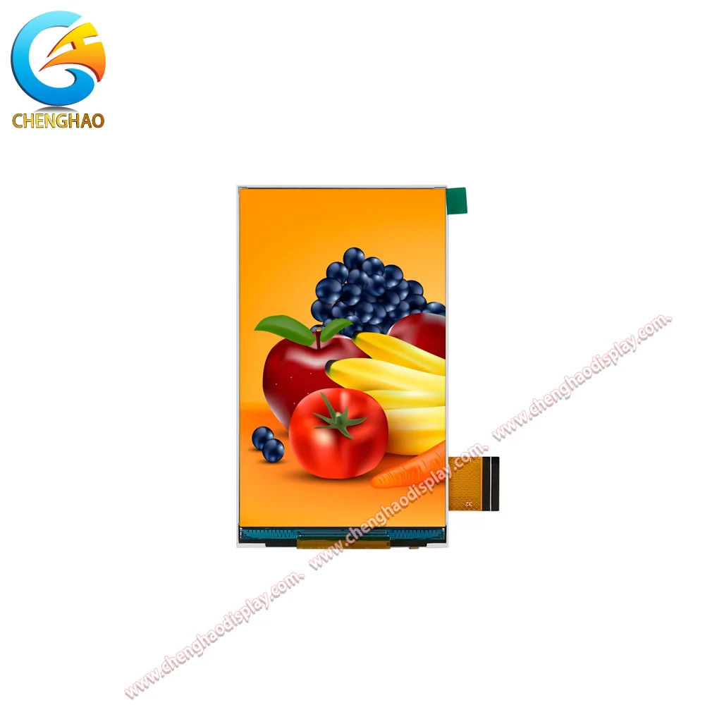
Powered-on view of the display screen
|
| CH450FW06A – 4.5 inch – TFT LCD | |
Projects slip badly when a vendor swaps touch controllers without notice, because every driver you tested breaks at once. At Chenghao Display, once a sample is signed off, the touch IC, firmware version and stack-up are locked. Small pre-production batches are supported as well, so full system validation can finish before volume ramp.
If a supplier hits any of these, proceed carefully:
Chenghao Display builds PCAP modules around the real pain points of embedded development rather than around a catalogue. Standard panels cover 2.4″ up to 7″ and larger. I2C is the main touch interface, compatible with STM32, ESP32 and other common embedded hosts. Air-bonded and optically bonded options are both available, along with wide temperature grades and custom FPC, cover glass and surface coatings for OEM HMI projects.
The engagement is not box-and-ship. Engineering support covers stack reviews, touch parameter tuning, driver debugging and EMI troubleshooting. A touch subsystem that behaves predictably is what lets a firmware team spend its time on sensing logic and core product function instead of on integration archaeology.
Q1: What should engineers define before requesting a capacitive touch panel quote?
Define the host platform, touch interface and logic level, operating environment, required touch behaviour, cover-glass stack, bonding method, ingress-protection target and power budget. These constraints determine whether a given panel and controller can be integrated reliably, and they are more decisive than screen size.
Q2: Why does the touch controller matter beyond the sensor glass?
The controller provides the filtering, calibration, water handling, glove algorithms and firmware settings that define the noise margin. Engineers should confirm that parameters can be tuned for the cover lens, stack-up and electrical environment of the finished product, and that the controller part number and firmware revision are documented.
Q3: Which stack-up and bonding choices affect touch reliability most?
Cover glass thickness and the bonding method have the largest effect. Above roughly 1.5 mm of cover glass, controller recalibration is normally required. Optical bonding removes air-gap reflections, reduces fogging and stabilises touch under vibration; air bonding suits low-cost indoor products with a stable enclosure environment.
Q4: What supplier evidence and support should be requested before production?
Request samples that match the production BOM, working drivers or example code, register maps, tuning guidance, and environmental and ESD test records. The approved controller, firmware and stack-up should remain locked through production, and pre-production batches should be available for full system validation.
Q5: Why do ghost touches appear only after the unit is assembled?
Because the cause is usually system noise rather than the panel: switching regulators, motor drives, long FPC runs or a poor ground reference all shift the capacitance the controller measures. The controller compensates by recalculating its baseline until a genuine press no longer stands out. Bench tests on an isolated panel cannot reproduce this, so controller tuning and EMC work have to be done on the assembled unit.